|

PROGRAMMABLE LOGIC CONTROLLER
with
embedded BASIC interpreter
CONTENTS
1. INTRODUCTION
Controller with embedded Basic interpreter (PLC-BASINT) is a
compact device that can operate as a PLC (program logic controller) for home
automation, control, etc. For example, this one can dial-up by modem to the
remote computer and send the status of the controlled system, can control some
processes, temperature regulation, battery charging, can be used for educations
and hobby purposes.
PLC-BASINT has analogue and discrete input/output
and an RS232 interface to communicate with other devices and to reflash a
control program. The control program is a text version of BASIC language. The
main task of the controller is to interpret BASIC commands. The TBC version of
the BASIC language has commands to operate with discrete I/O, ADC and PWM. The
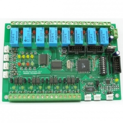
view of controller PCB is shown below in the figure 1.

Figure 1
The main feature of this controller is that users do not need
any special hardware and software tools. For program writing they can use any
text editor, NotePad for example. HyperTerminal is enough for program
downloading. Both of these programs are standard MS Windows applications. The
interpreter BASINT converts the user Basic program to the internal format at the
download stage. That allows reduce program size and get fast speed interpreting.
Technical details:
| 1. Number of discrete optocoupled inputs 5..15V |
8 |
| 2. Number of discrete relay outputs |
8 |
| 3. Number of analogue inputs 0…5V |
4 |
| 4. LEDs for user purpose |
4 |
| 4. DIP-switch. bits for user purpose |
7 |
| 5. Communications: |
2xRS232 or |
| |
1xRS485 and 1xRS232
|
| 7.The language of embedded interpreter |
Basic BASINT
|
| 8.Size of user program area, kilobytes, more than |
32 |
| 9. Simple command operating time, less than uSec |
150 |
| 10 Basic program storage place |
Program Flash |
Schematic in PDF
format
Controller external connections:

Figure 2
4. PROGRAM DOWNLOADING
HyperTerminal or another terminal application must be set up as shown
below:
Baud rate 57600 bps
Data/Stop bits 8/1
Parity None
Flow
Control Hardware
Terminal emulation ANSII / VT100
Add sent CR with LF

Figure 3
There are two ways to download.
The first one is by using the text file
sending option of the terminal.
The second way is downloading using paste
from the clipboard if you are using Windows HyperTerminal, for
example.
1.Make sure that write protect jumper is open.
2.Connect the
controller to PC by RS232 cable.
3.Power it up.
4.Start terminal
application.
5.Press the reset button on the controller.
The start page
appears in the terminal window.
6. Press menu option 2 to force the
controller be waiting for input text.
7. Send a program by using the text
file sending option of the terminal or paste text from the clipboard.
8.
Press menu option 1 to list the downloaded program.
9. Press menu option 3 to
run the downloaded program.
10. Close write protect jumper. It
alows:
- protect program;
- diasable start page screen;
-
automatically sart program when the controller is powered up.
This is starting page on HyperTerminal with controller
connected to PC serial port.

Figure 4
2. AVR BASINT. COMMANDS AND FUNCTIONS
There are some features of BASINT. - Program lines don’t have numbers. Line
numbers are using only for label’s mark.
Numbers:
All
numbers are the signed integers in a range from -32767 up to +32767.
There
are three forms of numbers representation:
- Decimal;
- Hexadecimal,
numbers have a prefix &H;
- Binary, numbers have a prefix &B;
Variables:
There are 26 variables denoted by the letters
A through Z. These are represented internally as 16-bit, two's-complement
integers.
There are up to 26 one-dimensional arrays. Size of arrays must be
defined before using. Maximum size depends of current free memory. The array
elements are accessible by an index in the parentheses. For example: A(0),
B(18). Note that A an A(n) are the different variables.
Operators
Arithmetic:
+
addition
- subtraction.
* multiply
/ integer division (note that
14/5 = 2
MOD - remainder from division (14 MOD 5 = 4).
AND – bit-wise
logical AND (3 AND 6 = 2)
OR – bit-wise logical OR
XOR – bit-wise
logical XOR
Compare:(using only with operator
IF):
= equal
<> (or ><) not equal
> more
<
less
>= (=>) more or equal
<= (=<) less or
equal
Expressions:
Expressions are formed with
numbers and variables with arithmetic operators between them. Operators of
comparison cannot be used in expressions. Parentheses can be used to alter the
order of evaluation.
Labels:
Label is a number from 0 to
32767. Labels must be set before line that is a point to jump or is a start line
of subroutine. It is not recommended to number all of the lines the labels table
is limited up to 64 labels.
| BASINT
KeyWord |
Description |
Can be used
in PLC-BASINT |
|
ABS
|
Returns absolute value |
Yes |
|
ADC
|
Reads meassured value from the current channel ADC |
Yes |
| AT |
Sets the position of the printing symbol for PRINT operator |
Yes |
| ATTR |
Sets the console output attributes |
Yes |
| BCD |
Puts to the console a value in BCD form |
Yes |
| BIN |
Puts to the console a value in BIN form |
Yes |
| CHR |
Sends symbol to the console by symbol code that is result of
expression.
CHR is an element of the output list for PRINT operator |
Yes |
| CLEAR |
Sets pin logic level to zero |
Yes |
| CLS |
Clears the screen and move cursor to top left corner |
Yes |
| DATA |
Specifies constant values to be read by READ operator |
Yes |
| DEFPIN AS |
Defines the pin function of the controller pins |
No |
| DELAY |
Forms delay |
Yes |
| DELETEVECTOR |
Disconnects the a handler code from vector and disables corresponding
interrupt |
Yes |
| DIM |
Defines an array size |
Yes |
| DISABLE |
Disables interrupts |
Yes |
| ENABLE |
Enables interrupts |
Yes |
| END |
Finishes the program execution |
Yes |
| FOR
TO NEXT |
Loop operator |
Yes |
| GETATOMIC |
Gets value from a variable used in an interrupt |
Yes |
| GOTO |
Unconditional branch |
Yes |
| GOSUB |
Calls subroutine |
Yes |
| HEX |
Puts to the console a value in hexadecimal form |
Yes |
| HIGH |
Returns high byte of expression result |
Yes |
| IF
THEN ELSE |
Condition branch operator |
Yes |
| INK |
Sets the symbol color |
Yes |
| INKEY |
Checks the console buffer for the received symbols |
Yes |
| INLINE |
Creates block of machine code |
Yes |
| INPUT |
Waits for input value |
Yes |
| INTERRUPT |
Creates the block of a machine code at a stage of program
loading.
Connects a code to a vector at a stage of execution |
Yes |
| LASTERROR |
Returns last error or critical situation code |
Yes |
| LOW |
Returns low byte of expression result |
Yes |
| PAPER |
Sets the background color |
Yes |
| PEEK |
Reads byte from memory or I/O port |
Yes |
| POKE |
Writes byte to memory or I/O port |
Yes |
| PRINT |
Prints the messages and the values on the console |
Yes |
| PULSEIN |
Returns pulse width on the controller pin |
Yes |
| PULSEOUT |
Forms pulse on the pin |
Yes |
| PUTATOMIC |
Assigns value of variable used in interrupt subroutine |
Yes |
| PWM |
Puts a digital value out to the PWR channel |
No |
| READ |
Reads DATA and moves pointer to next point |
Yes |
| READEEPROM |
Reads byte from the address in EEPROM |
Yes |
| REM |
Comments line. Interpreter skips the rest of code in this line |
Yes |
| RESTORE |
Allows read the DATA block more than one time.
Sets the pointer at the
needed labeled block of data |
Yes |
| RETURN |
Returns from subrouting |
Yes |
| ROL |
Shifts value of variable left. The LSB is set to 0 |
Yes |
| ROR |
Shifts value of variable right. The MSB is set to 0 |
Yes |
| SCALE |
Performs the scaling of variable |
Yes |
| SETADMUX |
Sets the analog multiplexer up |
Yes |
| SET |
Sets pin logic level to one |
Yes |
| SHIFTIN |
Returns the incoming sequence of bits |
No |
| SHIFTOUT |
Outputs contents of a variable as sequence of bits |
No |
| STOP |
Stops the program execution, clears receiving buffer,
starts after
getting new symbol in the input buffer |
Yes |
| TEST |
Reads pins logic level |
Yes |
| TOGGLE |
Switches pin logic level to the inverted state |
Yes |
| TWIINIT |
Iinitializes TWI (I2C) |
No |
| TWIREAD |
Reads byte from TWI (I2C) device. ACK/NACK generate |
No |
| TWISTOP |
Generates STOP condition on SDA and SCL pins |
No |
| TWIWRITE |
Sends byte to TWI (I2C) device |
No |
| WAITKEY |
Is waiting for a single symbol. Returns the code of received symbol |
Yes |
| WRITEEEPROM |
Writes byte to the address in EEPROM |
Yes |
2.1 CONSOLE INPUT/OUTPUT
Action:
Clears the screen and move cursor to top left
corner
Syntax:
CLS
Action:
Prints the message on the
console
Syntax:
PRINT [output list]
The elements
of the output list can be separated by semicolon that allows output more than
one variables or strings at one line without spaces between the elements.
Semicolon at the end of the line cancels adding CR and LF.
The elements of
the output list can be separated by comma that inserts number of spaces to set
output to the next position of tabulation. Comma at the end of the line cancels
adding CR and LF.
Examples:
| PRINT |
Line feed |
| PRINT “This message” |
printed: This message |
| PRINT “X=”;X; “ Y=”;Y; |
printed: X=(value of X) Y=(value of Y) |
| PRINT X,Y,Z, |
(value of X) (value of Y) (value of Z) |
Action:
Sets the position of the printing symbol for
PRINT operator
Syntax:
PRINT AT(x,y);[list]
x – row
position (from 1 to 80)
y – column position (from 1 to
24)
Example:
| PRINT
AT(35,12);“This msg”; AT(1,1); |
Print "This msg" in the center of the screen and set
cursor to the left/up corner |
Action:
Sends symbol to the console by its code that is
result of expression. Using with PRINT operator
Syntax::
PRINT [list1; or ,] CHR(val)[;
or , [list2]]
val – symbol code from 0 to 255. All another integer values
will be got as a low byte of word
Example:
FOR I=32 TO
127
PRINT
I,CHR(I)
NEXT |
Print symbol codes and symbol
itself |
Action:
HEX – puts to the console a value in
hexadecimal form,
BCD - puts to the console a value in BCD form,
BIN -
puts to the console a value in BIN form.
Functions HEX, BCD, BIN are the
elements of output list for PRINT
operator.
Синтаксис:
PRINT [list1; or ,]
HEX(value, digits)[; or , [list2]]
PRINT [list1; or ,] BCD(value, digits)[;
or , [list2]]
PRINT [list1; or ,] BIN(value, digits)[; or , [list2]]
value – value or expression
digits – number of printed digits
Example:
10 INPUT X
PRINT X,HEX(X,4);BIN(X,16)
GOTO 10 |
Print value in different
formats |
Action:
Sets the console output
attributes
Syntax:
ATTR expression
An expression defines output attributes:
0 – standard brightness
1 – more light brightness
4 – underscore
5 –
blinking
7 – color inverting
8 – set color of symbol and background the
same
Action:
Sets color attributes for console output
INK –
sets the symbol color
PAPER – sets the background
color
Syntax:
INK expession
PAPER
expession
An expession defines the color
0 – black
1 – red
2 – green
3 – yellow
4 – blue
5 –
magenta
6 – cyan
7 – white
Note. Using AT, CLS, ATTR, PAPER, INK allows change
attributes on ANSI terminal, as console. Most terminals program can support this
mode.
Action:
Waits for input value. Puts value to the variable
after receiving CR
Syntax:
INPUT ["Invite msg",]
variable
Examples:
| INPUT X |
Print “?” and wait for value |
| INPUT “X=”,X |
Print X= and wait for value |
Action:
Checks console buffer for the received symbols.
Return –1 if empty and symbol’s code if
not.
Syntax:
Variable =
INKEY()
Examples:
| A=INKEY() |
Read buffer |
|
10 C=INKEY()
IF C=-1 THEN GOTO 10
|
Wait for a symbol |
|
10 C=INKEY()
IF C<>-1 THEN GOTO 20
REM Do some background
task
GOTO 10
20 REM Do something upon received symbol
GOTO 10
|
Waiting for symbol and doing something
background |
Action:
Is waiting for a single symbol. Returns the code
of received symbol.
Syntax:
Variable =
WAITKEY()
Examples:
| A=INKEY() |
Wait for symbol |
2.2 PROCESS CONTROL OPERATORS
Action:
Condition branch operator
Should be written in
one line only.
Syntax:
IF condition THEN operator1 [ELSE
operator2]
Examples:
| IF X<10 THEN X=X+1 |
If true then expression |
|
IF X=0 THEN GOTO 100 ELSE GOTO 200
|
|
|
IF Z=65 THEN GOSUB 200
|
If true then call subroutine on label
200 |
Action:
Loop
operator
Syntax:
FOR Variable =
expression1 TО expression 2
some repeating
actions
NEXT
Note.
Step = 1 always
Examples:
|
FOR I=32 TO 127
PRINT
CHR(I),I
NEXT
|
Print symbols with code from 32 to
127 |
Action:
Unconditional
branch
Syntax:
GOTO
label
Example:
Action:
Calls
subroutine
Syntax:
GOSUB
label
Example:
Action:
Returns from
subrouting
Syntax:
RETURN
Example:
Action:
Finishes the program
execution
Syntax:
END
Examples:
Action:
Stops the program execution, clears receiving
buffer, starts after getting new symbol in the input buffer
Syntax:
STOP
Examples:
Action:
Comments line. Interpreter
skips the rest of code in this line.
Syntax:
REM [any string]
operator : REM
[any string]
Examples:
|
REM any text
|
Do nothing in this line of program
|
| A=10: REM any text |
Does only operator before REM |
Action:
Forms delay 1..65535 mSec
Syntax:
DELAY
expression
Examples:
|
DELAY 100
|
Forms delay 100 mSec
|
2.3 DATA
Action:
Defines an array
size
Syntax:
DIM
list
Note:
Maximum size of
array depends of available memory and controller type
|
|
Small
|
Mini
|
Maxi
|
|
Base crystal
|
ATMEGA16
|
ATMEGA32
|
ATMEGA64
|
|
Size of available memory
|
140 bytes/
70 elements
|
1000 bytes/
500 elements
|
To be defined
|
Examples:
| DIM A(10),B(20) |
Array A – reserved memory for 10 elements
Array B - reserved memory for
20 elements
|
Action:
Specifies constant values to be read by READ
operator. Note that max length of data line cannot be more than 64 symbols per 1
line. Max lines of data limited only of available flash memory.
Syntax:
DATA
list
Pointer sets to begin of first data block when program
starts
Examples:
Action:
Reads DATA and moves pointer to next
point
Syntax:
READ
list
Example:
Action:
Allows read the DATA block more
than one time. Sets the pointer at the needed labeled block of
data.
Syntax:
RESTORE [label]
RESTORE without parameters sets pointer to begin of the first data
block.
Examples:
100 DATA
1,2,3,4,5,6
DATA
7,8,9
110 DATA
555,777,888
….
RESTORE
110
|
Set pointer to DATA value 555
|
| RESTORE |
Set pointer to DATA value 1 |
Action:
Writes byte to the address in
EEPROM
Syntax:
WRITEEEPROM address,
byte
Action:
Reads byte from the address in
EEPROM
Syntax:
Variable =
READEEPROM(address)
|
|
Small
|
Mini
|
Maxi
|
|
Base crystal
|
ATMEGA16
|
ATMEGA32
|
ATMEGA64
|
|
Size of EEPROM, byte
|
512
|
1024
|
2048
|
2.4 INTERRUTS and MACHINE CODE
Action:
Enables
interrupts
Syntax:
ENABLE
Action:
Disables
interrupts
Syntax:
DISABLE
Action:
Creates block of machine code
on program downloading stage. A few lines of INLINE in any place of program
create consequtive block of a code in special area of memory. If the block of a
code is formed by several lines INLINE, it is necessary to take care, that
interpreter will look only on first of them. The rest of INLINEs should be
hidden after operators RETURN or GOTO
The block of a code should be issued as
the subroutine, last operator should be operator RET.
Communication with
BASIC variables is simple, registers R16, R17 contain the pointer to variable A.
A principle of formation of the address of any of 26 (from A up to Z) scalar
variables following:
Address = value of R16R17 + 2 * (symbol code - 65)
Синтаксис:
INLINE opcode1,
opcode2….
Example:
| 10 INLINE opcode1, opcode2…. |
Simple case, code block is formed by single operator INLINE
|
10 INLINE opcode1, opcode2….
RETURN
INLINE opcoden,
opcoden+1…. |
Block of code is formed by two operators INLINE, so the second operator
is hidden after RETURN. |
Note. It is possible to automate process of creating INLINE blocks. Just use
bin2line.exe to convert machine code to INLINE operators.
It is shown below:
avrasm32 -fI -l %1.lst -o %1.hex %1.asm
hex2bin %1.hex %1.bin
bin2line
-i %1.bin -o %1.bas
This is a command file that starts process of conversion
from asm code to INLINE code. Avrasm32.exe is an assembler from AVR STUDIO. This
one assembles to code directly. For example, we will create procedure to access
to 16-bit registers of AVR micro. Value of variable A is writing to register
OCR1A.
.include "m64def.inc"
mov r30,r16
mov r31,r17
ld
r18,z+
ld r19,z+
cli
out OCR1AH,R19
out
OCR1AL,R18
sei
ret
INLINE block after conversion:
INLINE 12256,12273,37153,37169,38136,48443
INLINE
48426,38008,38152
You need put it in BASIC program, add label before the first INLINE and write
RETURN or GOTO (as you need) after the first INLINE
200 INLINE
12256,12273,37153,37169,38136,48443
RETURN
INLINE
48426,38008,38152
Action:
Creates the block of a machine code at a stage of
program loading.
Connects a code to a vector at a stage of execution.
If
code of interrupt handler does not fit in one line, it is possible to continue
in next line, but using INLINE operator. The line with INTERRUPT should be
separated from other code by one of operators RETURN, GOTO as you need. At a
stage of execution the line with INTERRUPT should be interpreted once for
interrupti initialization. Requirements on registration of the block of a code
same as well as for operator INLINE. Can be simultaneously used up to 10
vectors. It is impossible to set interruptions For UART0 and TIMER0 as they are
used by system.
Syntax:
INTERRUPT
vector, opcode1,
opcode2….
Example:
INTERRUPT vector,
opcode1, opcode2…
200 INTERRUPT vector, opcode1,
opcode2…
RETURN
INLINE opcoden, opcoden+1…
|
The simpliest case is when the handler takes only one line
The operator INTERRUPT gets the start address of the code block and binds it
with needed vector.
|
Action:
Disconnects the a handler code from vector and
disables corresponding interrupt.
Syntax:
DELETEVECTOR
vector
Action:
Assigns value of variable used
in interrupt subroutine. During this action interpreter disables interrupts to
provide complete (atomic) updating a two-byte variable. It is necessary, as
operation of giving contains a chain of several commands which could be broken
off by the interrupt, providing access to the same
variable..
Syntax:
PUTATOMIC
var, value
Action:
Gets value from a variable used in an interrupt.
During this operator executing interrupts are disabled.
Syntax:
some_var =
GETATOMIC(var)
2.5 CONTROLER’S PINS ASSIGNMENT AND USE
|
Pin
number
|
Main function
|
Alternative
function
|
|
0
|
PA0
|
ADC0
|
|
1
|
PA1
|
ADC1
|
|
2
|
PA2
|
ADC2
|
|
3
|
PA3
|
ADC3
|
|
4
|
PA4
|
ADC4
|
|
5
|
PA5
|
ADC5
|
|
6
|
PA6
|
ADC6
|
|
7
|
PA7
|
ADC7
|
|
8
|
PB0
|
|
|
9
|
PB1
|
|
|
10
|
PB2
|
|
|
11
|
PB3
|
|
|
12
|
PB4
|
|
|
13
|
PB5
|
|
|
14
|
PB6
|
|
|
15
|
PB7
|
|
|
16
|
PC0
|
|
|
17
|
PC1
|
|
|
18
|
PC2
|
|
|
19
|
PC3
|
|
|
20
|
PC4
|
|
|
21
|
PC5
|
|
|
27
|
PD3
|
|
|
28
|
PD4
|
PWM0
|
|
29
|
PD5
|
PWM1
|
|
30
|
PD6
|
|
|
31
|
PD7
|
|
Action:
Defines the pin function of the controller pins.
The controller pins have numbering from zero up to some maximum value that
depends on the type of controller. The Sets of additional pin functions depends
on type of the controller too. See table to reference.
|
|
Small
|
Mini
|
Maxi
|
|
Type
|
ATMEGA16
|
ATMEGA32
|
ATMEGA64
|
|
Available pins
|
26
|
26
|
|
|
Pins allowed to change direction function DIN/DOUT
|
0..21, 27..31
|
0..21, 27..31
|
|
|
Pins allowed to set analog mode AIN
|
0..7
|
0..7
|
|
|
Pins allowed to set PWM function
|
28,29
|
28,29
|
|
Syntax:
DEFPIN pin AS type
Note.
| type |
function
|
|
DIN
|
Discrete input
|
|
DOUT
|
Discrete output
|
|
AIN
|
Analog input
|
|
PWM
|
Pulse width modulation
|
Example:
| DEFPIN 8 AS DOUT |
Sets pin #8 to operate as a discrete
output
|
Action:
Sets pin logic level to
zero
Syntax:
CLEARBIT
pin
Action:
Sets pin logic level to
one
Syntax:
SETBIT
pin
Action:
Switches pin logic level to the inverted
state
Syntax:
TOGGLE
pin
Action:
Reads pins logic
level
Syntax:
var = TESTPIN(pin)
Action:
Puts a digital value out to the PWR
channel
Syntax:
PWR pwm_pin,
value
Action:
Set the analog multiplexer
up
Syntax:
SETADMUX
value
Note.
value = reference source + channel
number
| Reference source |
|
|
0
|
pin AREF
|
|
64
|
pin AVCC
|
|
192
|
internal 2.56 volt
|
Action:
Reads meassured value from the current channel
ADC
Syntax:
var =
ADС
2.6 ACCESS TO INTERNAL RESOURCE OF MICROCONTROLLER
Action:
Writes byte to memory or I/O
port
Syntax:
POKE adr, val
Action:
Reads byte from memory or I/O
port
Синтаксис:
var =
PEEK(adr)
Note: You should reference to avr datasheet to get the
address of register. Remember there are two addresses: I/O and memory. PEEK and
POKE operate with memory address and and you need to add 32 to get I/O address.
2.6.1 Access to the 16-bit registers
Access to the 16-bit registers of avr micro has features. It uses hardware
temporary 8-bit register. From the program point of view, there are some rules
to access:
1. Use IN and OUT assembler operators.
2. For write: access to
the highest register is first.
3. For read: access to the lowest register is
first.
This is an example of two subroutines for access register OCR1A
using BASIC variable A:
REM .include
"m64def.inc"
REM mov r30,r16
REM mov r31,r17
REM ld
r18,z+
REM ld r19,z+
REM cli
REM out OCR1AH,R19
REM
out OCR1AL,R18
REM sei
REM ret
REM WRITE to
OCR1A
200 INLINE 12256,12273,37153,37169,38136,48443
RETURN
INLINE
48426,38008,38152
REM .include
"m64def.inc"
REM mov r30,r16
REM mov r31,r17
REM cli
REM in R18,OCR1AL
REM in R19,OCR1AH
REM sei
REM st z+,
r18
REM st z+, r19
REM ret
REM READ from
OCR1A
300 INLINE 12256,12273,38136,46378,46395,38008
RETURN
INLINE
37665,37681,38152
2.7 MATH ROUTINES
Action:
Returns high byte
Syntax:
var =
HIGH(expression)
Action:
Returns low byte
Syntax:
variable =
LOW(expression)
Action:
Returns absolute value
Syntax:
variable =
ABS(expression)
Action:
Shifts value of variable left. The LSB is set to
0.
Syntax:
ROL variable, number of
shifts
Action:
Shifts value of variable right. The MSB is set to
0.
Syntax:
ROR variable, number of
shifts
Action:
Performs the scaling
Syntax:
SCALE
Variable, multiplier, divider
Examples:
SCALE X,100,Y
|
Calculates percent of number X from number Y. First X * 100 and put result
into 32 bit temporary variable M32, then M32 / Y and put result into X
|
|
SCALE X,1000,Y
|
The same, but 10 times more
precision
|
2.8 SOME BASIC EXTENTIONS
Action:
Returns pulse width on the controller pin unit
that are approximately 1 uS at frequency of quartz 14.745 MHz
Синтаксис:
var =
PULSEIN(pin, option, timeout)
Note
option |
|
|
0
|
Waiting for raise edge and measurement pulse width
|
|
1
|
Waiting for fall edge and measurement of pulse
width
|
Action:
Forms pulse on the
pin
Syntax:
PULSEOUT pin, duration
pin – pin number
duration - duration in uSec for resonator 14.745 MHz
Action:
Returns the incoming sequence of
bits
Syntax:
var =
SHIFTIN(data_pin, clock_pin, bits, delay, option,
timeout)
Note:
data_pin |
incoming data
|
|
clock_pin
|
Synchro, mode defined in option
|
|
Bits
|
number of bits
|
|
Delay
|
Delay in uSec for resonator 14.745 MHz
|
|
Option
|
Mode of synchronization:
clk_pin – output:
0 – the highest
bit the first on rising edge
1 – the highest bit the first on falling
edge
2 – the lowest bit the first on rising edge
3 – the lowest bit the
first on falling edge
clk_pin – input:
option = option + 4
|
|
timeout
|
Time in mSec on which expiration function returns a zero and
variable LASTERROR accepts value 1. Value timeout is actual when clk_pin works
as synchro_input
|
Action:
Outputs contents of a variable as sequence of
bits
Syntax:
SHIFTOUT
var, data_pin, clock_pin, bits, delay, option
Note:
Var |
Variable contains a value to be converted to consecutive
code
|
|
Data_pin
|
Output consecutive data
|
|
clock_pin
|
Synchro, mode defined in option
|
|
Bits
|
number of bits
|
|
Delay
|
Delay in uSec for resonator 14.745 MHz
|
|
Option
|
Mode of synchronization:
clk_pin – output:
0 – the highest
bit the first on rising edge
1 – the highest bit the first on falling
edge
2 – the lowest bit the first on rising edge
3 – the lowest bit the
first on falling edge
|
2.9 TWO WIRE INTERFACE
Action:
Iinitializes TWI
(I2C)
Syntax:
TWIINIT bps,
prescale
bps – number for bps needed
prescale - can be defined from
equation:
SCL frequency = CPU Clock frequency / (16 + 2(bps) * 4^prescale)
Action:
Generates START condition on SDA and SCL pins
Syntax:
TWISTART
Action:
Sends byte to TWI (I2C)
device
Syntax:
TWIWRITE байт
Action:
Reads byte from TWI (I2C) device. ACK/NACK
generate
Syntax::
var =
TWIREAD(ack)
Parameter ack:
0 – NACK
1 – ACK
Action:
Generates STOP condition on SDA and SCL
pins
Syntax::
TWISTOP
Example:
| |
print
"***************************"
print "* DS1339U TWI TEST *"
print
"***************************"
DIM A(16)
TWIINIT 16,2
TWISTART
rem
DS1339U Slave address to write
TWIWRITE &HD0
rem Trickle Charger
Register (10h)
TWIWRITE &H10:TWIWRITE &B10100101
TWISTOP
10
A=0:TWISTART:TWIWRITE &HD0:TWIWRITE A:TWISTOP
TWISTART:TWIWRITE
&HD1
FOR i=0 to
5
A(i)=TWIREAD(1)
NEXT
A(6)=TWIREAD(0):TWISTOP
PRINT "Year:";
if
(A(5)AND 128)=0 then print "19";else print "20";
print bcd(a(6),2);
print
" Month:";bcd(a(5) AND 127,2);
print " Date:";bcd(a(3),2);"
Day:";bcd(a(3),2);
print " ";bcd(a(2),2);":";bcd(a(1),2);":";bcd(a(0)
GOTO 10 |
2.10 DIAGNOSTICS
At execution of the program there can be situations at which the interpreter
stops the work and sends the message on an error in which the code and number of
a line is underlined.
|
Error code
|
Error
|
|
0
|
Syntax error
|
|
1
|
Unbalanced parentheses
|
|
2
|
No expression present
|
|
3
|
Equals sign expected
|
|
4
|
Not a variable
|
|
5
|
Label table full
|
|
6
|
Duplicate label
|
|
7
|
Undefined label
|
|
8
|
THEN expected
|
|
9
|
TO expected
|
|
10
|
Too many nested FOR loops
|
|
11
|
NEXT without FOR
|
|
12
|
Too many nested GOSUBs
|
|
13
|
RETURN without GOSUB
|
|
14
|
Array not defined
|
|
15
|
Duplicatearray definition
|
|
16
|
Out of memory
|
|
17
|
Array index out of range
|
|
18
|
Pointer out of DATA
|
|
20
|
Can not assign more vectors
|
Action:
Returns last error or critical situation
code
Syntax:
var =
LASTERROR()
Note::
|
Error code
|
Error
|
|
0
|
No errors
|
|
1
|
Timed out (PULSEIN, SHIFTIN)
|
|
2
|
TWI error
|
3. PRE-PROCESSOR
BASIC language is an extremely simple language, but it is difficult to write
big programs by BASIC because the variables length is too short. The best case
is when the possible length allows to write “selfcomment” variables. But, long
variables, labels could be the cause of slow speed interpreting and resource
consuming. A special program-converter can help to resolve this coflict. Our
interpreter will still working with short names, but we will work with long
names by placing the lines with the preprocessor instruction DEFINE in the
program text as shown below:
DEFINE some_long_name = D ‘ defines self
comment variable
DEFINE one_more_long_name = 100 ‘ defines constant or
label
You can use the apostrophes to start a comment line. At the end you
will get something like the program shown below:
|
|
'--------------------------------------------------------
'
TBC GROUP 2006
'
SHIFTOUT
TEST
'
'--------------------------------------------------------
'
Clock options
define MSB_FIRST_POSITIVE = 0 ' the highest bit first at raise
edge
define MSB_FIRST_NEGATIVE = 1 ' the highest bit first at falling
edge
define LSB_FIRST_POSITIVE = 2 'the lowest bit first at raise
edge
define LSB_FIRST_NEGATIVE = 3 'the lowestest bit first at falling
edge
define TotalBits =
N ' Количество бит от 1 до 16
define SrcData = A ' variable with a source
wordvalue
define DataPin = D ' data pin number
define ClockPin = C
' clock pin number
define Options = B ' options
define PulseDelay =
100 ' defines pulse width that is 2 * PulseDelay
define MainLoop = 10 '
Just a name of label 10
CLS
PRINT
"*******************************"
PRINT "* SHIFTOUT TEST
*"
PRINT "*******************************"
input "DATA
PIN=",DataPin
DEFPIN DataPin AS DOUT:SET DataPin
input
"CLOCK PIN=",ClockPin
DEFPIN ClockPin AS DOUT:CLEAR
ClockPin
MainLoop
input "TOTAL BITS=",TotalBits
input
"options=",options
input "data=",SrcData
shiftout
SrcData,DataPin,ClockPin,TotalBits,PulseDelay,Options
GOTO
MainLoop
|
|
This text needs to be cnvereted before downloading into controller. First we
save text of program as shift.bas for example . Then in a command line we can
type:
BASPREP.EXE –I shift.bas –O shift.out
Note. BASPREP.EXE must be placed in the same catalogue or be
visible of a current arrangement. You can put to C:WINDOWS for example.
We will get something like shown below as a result of conversion.
|
|
CLS
PRINT"*******************************"
PRINT"*
SHIFTOUTTEST *"
PRINT"*******************************"
INPUT "DATA
PIN=",D
DEFPIN D AS DOUT:SET D
INPUT "CLOCK PIN=",C
DEFPIN C AS
DOUT:CLEAR C
10 INPUT "TOTAL BITS=",N
INPUT "options=",B
INPUT
"data=",A
SHIFTOUT A,D,C,N,100,B
GOTO 10
|
|
The preprocessor eliminates all of the comments and substitute the long names
for theirs short values.
|


 현재위치 :